- URDF简介
ROS及其社区的许多有用的功能都涉及诸如冲突检查collision checking和动态路径规划dynamic path planning之类的事情。 采用独立于代码且易于理解的方式来描述机器人及其单元的几何形状通常非常有用。统一机器人描述格式Unified Robot Description Format(URDF)是当今最受欢迎的格式。 接下来将创建一个简单的机器人单元,我们将在此单元上进行扩展并在以后用于实际用途。
本练习中描述的几何将用于:
1.执行碰撞检查
2.了解机器人运动学
3.执行转换数学,目标是描述一个具有以下功能的工作单元(workcell):
(1).名为world的基础框架(origin frame)
(2).具有“工作台”几何形状的独立框架(扁平的矩形棱柱)
(3). 称为camera_frame的框架(可选几何),其方向使其Z轴相对于世界的Z轴翻转
1. 通常,将非代码的描述文件放入自己的“支持support”包中。 URDF通常会进入其自己的子文件夹“ urdf /”。 请参阅abb_irb2400_support程序包。 将urdf子文件夹添加到您的应用程序支持包中。
2. 在myworkcell_support/urdf/ 文件夹中建立workcell.urdf 文件,并插入XML 框架:
<?xml version="1.0" ?>
<robot name="myworkcell" xmlns:xacro="http://ros.org/wiki/xacro">
</robot>
3. 添加所需的链接。 请参见ABB2400的irb2400_macro.xacro示例。 请记住,所有URDF标签都必须放在<robot> ... </ robot>标签之间。
3.1. 将世界框架world frame添加为“虚拟链接virtual link”(无几何图形)。
<link name="world"/>
3.2. 添加table框架,并确保同时指定碰撞和视觉几何collision & visual geometry标签。 请参阅XML规范中的框类型。
<link name="table">
<visual>
<geometry>
<box size="1.0 1.0 0.05"/>
</geometry>
</visual>
<collision>
<geometry>
<box size="1.0 1.0 0.05"/>
</geometry>
</collision>
</link>
3.3. 将camera_frame框架添加为另一个虚拟链接(无几何形状)。
<link name="camera_frame"/>
3.4. 用一对固定关节连接您的链接,在world_to_camera关节中使用rpy标签设置其方向。
<joint name="world_to_table" type="fixed">
<parent link="world"/>
<child link="table"/>
<origin xyz="0 0 0.5" rpy="0 0 0"/>
</joint>
<joint name="world_to_camera" type="fixed">
<parent link="world"/>
<child link="camera_frame"/>
<origin xyz="-0.25 -0.5 1.25" rpy="0 3.14159 0"/>
</joint>
添加链接后,通过RViz可视化URDF,以验证事物的外观是否符合预期:
roslaunch urdf_tutorial display.launch model:=`rospack find myworkcell_support`/urdf/workcell.urdf
- XACRO工作单元
接下来我们将创建一个代表简单机器人工作单元的XACRO文件。 这将演示URDF和XACRO元素。
之前我们创建了一个仅包含静态几何图形的工作单元。接下来,我们将使用XACRO工具添加UR5机械手部件。
1.将您在上一个示例中创建的*.urdf文件转换为带有xacro扩展名的XACRO文件。
1.1. 将上一练习中的workcell.urdf文件重命名为workcell.xacro。
1.2. 将ur_description包引入ROS环境:
cd ~/catkin_ws/src
git clone https://github.com/ros-industrial/universal_robot.git
catkin build
source ~/catkin_ws/devel/setup.bash
2. 包含一个包含UR5的xacro-macro定义的文件。
2.1. 找到实现UR5宏的xacro文件,并将其包含在新重命名的workcell.xacro文件中。 在workcell.xacro文件顶部附近的<robot>标记下添加以下包含行:
<xacro:include filename="$(find ur_description)/urdf/ur5.urdf.xacro" />
2.2.在URDF模型中,包含ur5.urdf.xacro文件实际上并不会创建UR5机械手。 它定义了一个宏,但是仍然需要调用该宏来创建机器人链接和关节。 (大多数宏将带有“ prefix”参数,以允许用户创建该宏的多个实例。)
3. 在工作空间中实例化UR5并将其连接到table链接。
3.1. 通过固定链接将UR5 base_link连接到现有的静态几何体。
<joint name="table_to_robot" type="fixed">
<parent link="table"/>
<child link="base_link"/>
<origin xyz="0 0 0" rpy="0 0 0"/>
</joint>
3.2. 创建一个新的urdf.launch文件(在myworkcell_support软件包中)以加载URDF模型并(可选)在rviz中显示它:
<launch>
<arg name="gui" default="true"/>
<param name="robot_description" command="$(find xacro)/xacro --inorder '$(find myworkcell_support)/urdf/workcell.xacro'" />
<node name="robot_state_publisher" pkg="robot_state_publisher" type="robot_state_publisher"/>
<node name="joint_state_publisher" pkg="joint_state_publisher" type="joint_state_publisher">
<param name="use_gui" value="$(arg gui)"/>
</node>
<node name="rviz" pkg="rviz" type="rviz" if="$(arg gui)"/>
</launch>
查看创建结果:roslaunch myworkcell_support urdf.launch
- 使用TF进行坐标变换
TF库是一种基本工具,可用于查找任何连接的框架之间的转换,甚至可以追溯到过去
我们的(模拟)摄像机返回的零件姿态信息在摄像机本身的光学参考框中给出。 为了使机器人能够处理这些数据,我们需要将数据转换为机器人的参考系。
具体来说,请在vision_node内编辑服务回调,以将最近的已知零件姿态从camera_frame转换为服务调用的base_frame请求字段。
1. 将tf指定为核心软件包的依赖项。
编辑package.xml(1行)和CMakeLists.txt(2行)
2. 将tf::TransformListener对象添加到vision节点(作为类成员变量)。
tf::Transform cam_to_target;
tf::poseMsgToTF(p->pose.pose, cam_to_target);
3. 将代码添加到现有的localizePart方法中,以将报告的目标姿势从其参考框架(“ camera_frame”)转换到服务请求框架:
3.1. 从上一个练习中删除占位符行,该练习将结果姿势设置为与上一条消息的姿势相等
- res.pose = p->pose.pose;
3.2. 或好或坏,ROS使用许多不同的数学库。 您需要将geometry_msgs::Pose的有线格式转换为tf::Transform object:
tf::Transform cam_to_target;
tf::poseMsgToTF(p->pose.pose, cam_to_target);
3.3. 使用lisenter对象从ARMarker消息(应为“ camera_frame”)中查找request.base_frame和参考帧之间的最新转换:
tf::StampedTransform req_to_cam;
listener_.lookupTransform(req.base_frame, p->header.frame_id, ros::Time(0), req_to_cam);
3.4. 使用以上信息,将对象姿态转换为目标框架。
tf::Transform req_to_target;
req_to_target = req_to_cam * cam_to_target;
3.5. 在服务响应中返回转换后的姿势。
tf::poseTFToMsg(req_to_target, res.pose);
4.运行节点测试transform。
catkin build
roslaunch myworkcell_support urdf.launch
roslaunch myworkcell_support workcell.launch
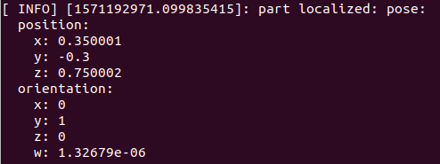
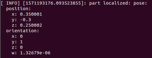
5. 更改workcell.launch中的“ base_frame”参数(例如更改为“ table”),重新启动workcell.launch文件,并注意不同的姿势结果。 完成后,将“ base_frame”参数更改回“ world”。
“base_frame” = world
“base_frame” = table
- 建立一个MoveIt!软件包
接下来,将创建一个MoveIt! 工业机器人的软件包。 该软件包创建将机器人与MoveIt!运动控制节点一起使用所需的配置和启动文件。 一般来说,MoveIt! 程序包不包含任何C ++代码。
MoveIt!是ROS的自由空间运动计划框架。 这是一种非常有用且易于使用的工具,可以在不碰撞任何东西的情况下规划空间中两点之间的运动。
接下来将为上一步中构建的UR5工作单元生成一个MoveIt程序包。 此过程主要涉及运行MoveIt!设置助手。目标是得到:
- 一个名为myworkcell_moveit_config的新软件包
(2) 具有一组的Moveit配置(“操纵器manupulator”),由UR5的base_link和base_link之间的运动链组成。
1. 启动MoveIt! Setup Assistant
roslaunch moveit_setup_assistant setup_assistant.launch
2. 选择“创建新的MoveIt配置包”,选择之前创建的workcell.xacro,然后选择“加载文件”。
3. 从上至下浏览左侧的标签。
3.1. 生成自碰撞矩阵。
3.2. 添加固定的虚拟基础节点。 例如
name = 'FixedBase' (arbitrary)
child = 'world' (should match the URDF root link)
parent = 'world' (reference frame used for motion planning)
type = 'fixed'
3.3. 添加一个名为manipulator的计划组,该组命名base_link和tool0之间的运动学链。 注意:请遵循ROS命名准则/要求,并且在任何地方都不要使用任何空格。
a.将运动学求解器设置为KDLKinematicsPlugin
3.4. 创建一些有名称的固定位置(例如“ home”,“ allZeros”等)以进行运动计划测试。
3.5. 不必添加末端执行器/夹具或被动接头。
3.6. 输入作者/维护者信息。
3.7. 生成一个新程序包,并将其命名为myworkcell_moveit_config。
确保在catkin_ws/src目录中创建包
MoveIt!的设置助手会生成一组文件,这些文件在启动时:
- 将工作空间描述加载到参数服务器。
- 启动节点move_group,该节点提供一套ROS服务和动作,以进行运动学,运动计划等。
- 一个内部仿真器,它在循环中发布最后计划的路径,以便其他工具(例如RViz)可视化。
本质上,MoveIt可以发布定义轨迹(随时间变化的关节位置)的ROS消息,但它不知道如何将该轨迹传递给硬件。
为此,需要定义一些额外的文件。
(1). Create a controllers.yaml file (myworkcell_moveit_config/config/controllers.yaml) with the following contents:
controller_list:
- name: ""
action_ns: joint_trajectory_action
type: FollowJointTrajectory
joints: [shoulder_pan_joint, shoulder_lift_joint, elbow_joint, wrist_1_joint, wrist_2_joint, wrist_3_joint]
(2). Create the joint_names.yaml file (myworkcell_moveit_config/config/joint_names.yaml):
controller_joint_names: [shoulder_pan_joint, shoulder_lift_joint, elbow_joint, wrist_1_joint, wrist_2_joint, wrist_3_joint]
(3). Fill in the existing, but blank, controller_manager launch file: (myworkcell_moveit_config/launch/myworkcell_moveit_controller_manager.launch.xml):
<launch>
<arg name="moveit_controller_manager"
default="moveit_simple_controller_manager/MoveItSimpleControllerManager"/>
<param name="moveit_controller_manager"
value="$(arg moveit_controller_manager)"/>
<rosparam file="$(find myworkcell_moveit_config)/config/controllers.yaml"/>
</launch>
(4). Create a new myworkcell_planning_execution.launch (in myworkcell_moveit_config/launch):
<launch>
<!-- The planning and execution components of MoveIt! configured to run -->
<!-- using the ROS-Industrial interface. -->
<!-- Non-standard joint names:
- Create a file [robot_moveit_config]/config/joint_names.yaml
controller_joint_names: [joint_1, joint_2, ... joint_N]
- Update with joint names for your robot (in order expected by rbt controller)
- and uncomment the following line: -->
<rosparam command="load" file="$(find myworkcell_moveit_config)/config/joint_names.yaml"/>
<!-- the "sim" argument controls whether we connect to a Simulated or Real robot -->
<!-- - if sim=false, a robot_ip argument is required -->
<arg name="sim" default="true" />
<arg name="robot_ip" unless="$(arg sim)" />
<!-- load the robot_description parameter before launching ROS-I nodes -->
<include file="$(find myworkcell_moveit_config)/launch/planning_context.launch" >
<arg name="load_robot_description" value="true" />
</include>
<!-- run the robot simulator and action interface nodes -->
<group if="$(arg sim)">
<include file="$(find industrial_robot_simulator)/launch/robot_interface_simulator.launch" />
<!-- publish the robot state (tf transforms) -->
<node name="robot_state_publisher" pkg="robot_state_publisher" type="robot_state_publisher" />
</group>
<!-- run the "real robot" interface nodes -->
<!-- - this typically includes: robot_state, motion_interface, and joint_trajectory_action nodes -->
<!-- - replace these calls with appropriate robot-specific calls or launch files -->
<group unless="$(arg sim)">
<remap from="follow_joint_trajectory" to="joint_trajectory_action"/>
<include file="$(find ur_modern_driver)/launch/ur_common.launch" >
<arg name="robot_ip" value="$(arg robot_ip)"/>
<arg name="min_payload" value="0.0"/>
<arg name="max_payload" value="5.0"/>
</include>
</group>
<include file="$(find myworkcell_moveit_config)/launch/move_group.launch">
<arg name="publish_monitored_planning_scene" value="true" />
</include>
<include file="$(find myworkcell_moveit_config)/launch/moveit_rviz.launch">
<arg name="config" value="true"/>
</include>
</launch>
- 通过RViz进行运动规划
RViz插件可在模拟机器人上计划和执行运动。
规划算法,RRTkConfigDefault算法通常更快。
环境障碍Environment Obstacles
- 调整目标状态以使机器人与障碍物(例如桌子)碰撞
- 请注意,碰撞链接显示为红色
- 由于该位置无法到达,您可以看到机器人在尝试寻找解决方案时通过不同的位置进行搜索
- 尝试在“计划”选项卡上禁用“Collision-Aware IK”设置
- 看到仍然检测到冲突,但是求解器不再搜索无冲突的解决方案
- 尝试规划穿过障碍物的路径
- 移动目标状态时禁用“碰撞感知IK”可能会有所帮助
- 如果机器人无法计划,请检查错误日志并尝试重复计划请求
- 由于默认计划器基于抽样,因此他们在每次执行时可能会产生不同的结果
- 您也可以尝试增加计划时间,以创建成功的计划
- 在这个更复杂的计划任务中尝试不同的计划算法
- 尝试为场景添加新的障碍:
- 在“场景对象”选项卡下,添加I-Beam.dae CAD模型
- 该文件位于industrial_training存储库中:~/industrial_training/exercises/3.4/I-Beam.dae
- 使用操纵手柄将工字梁移动到有趣的位置
- 按发布场景,将更新的位置推送到MoveIt
- 尝试绕过障碍物