Arduino作为开源硬件界的杰出代表,在此就不再赘述其普适性范畴了,本文我们着重介绍的是ApolloStudio如何与Arduino进行完美结合形成“双A”组合:Arduino作为执行单元控制着各种外设(外设电路如何设计不在本文讨论范畴),Arduino将外设的数据(温度,流量,电压,电流,状态信号等等),通过串口回传至ApolloStudio上显示,并形成图表或仪表盘等等,这里我们将分为两个部分进行分述。
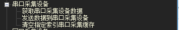
我们先预览下ApolloStudio的脚本工具箱里面即将应用到的技术点(串口采集设备跟串口通讯是两个不同的分支,主要区别在于通讯协议不同:串口采集设备的接收端是以回车换行结束,发送端自定义(适用于Arduino的Serial.println()函数);而串口通讯的接收和发送两端都是以0x02 + 数据内容(ascii码形式)+ 0x03结束):
小试牛刀
Arduino IDE自带了大量的示例程序,这里我们以Arduino Uno默认示例SerialEvent为例,我们打开Arduino IDE,找到文件》示例》Communication》SerialEvent示例,这里我们将示例代码原封不动贴出来便于参考:
/*Serial Event exampleWhen new serial data arrives, this sketch adds it to a String.When a newline is received, the loop prints the string and clears it.A good test for this is to try it with a GPS receiver that sends outNMEA 0183 sentences.NOTE: The serialEvent() feature is not available on the Leonardo, Micro, orother ATmega32U4 based boards.created 9 May 2011by Tom IgoeThis example code is in the public domain.http://www.arduino.cc/en/Tutorial/SerialEvent
*/String inputString = ""; // a String to hold incoming data
bool stringComplete = false; // whether the string is completevoid setup() {// initialize serial:Serial.begin(9600);// reserve 200 bytes for the inputString:inputString.reserve(200);
}void loop() {// print the string when a newline arrives:if (stringComplete) {Serial.println(inputString);// clear the string:inputString = "";stringComplete = false;}
}/*SerialEvent occurs whenever a new data comes in the hardware serial RX. Thisroutine is run between each time loop() runs, so using delay inside loop candelay response. Multiple bytes of data may be available.
*/
void serialEvent() {while (Serial.available()) {// get the new byte:char inChar = (char)Serial.read();// add it to the inputString:inputString += inChar;// if the incoming character is a newline, set a flag so the main loop can// do something about it:if (inChar == '\n') {stringComplete = true;}}
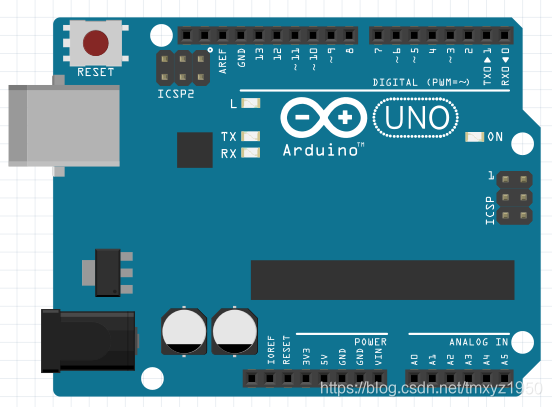
}硬件方面只需要用USB线将Arduino Uno的D型USB口连接上PC端的USB口即可,无需其他外设,在IDE中将SerialEvent程序下载至Uno中:
下面我们来看下ApolloStudio的简单配置,先添加脚本单元以及串口采集单元,串口采集单元设置如下(需根据实际情况调整串口参数使其与Arduino端的串口配置保持一致):
 编写脚本并在脚本单元中指定脚本文件路径:
#-*- coding: UTF-8 -*-
#加载内嵌模块
import clr,sys,time,datetimen = 0#循环函数体
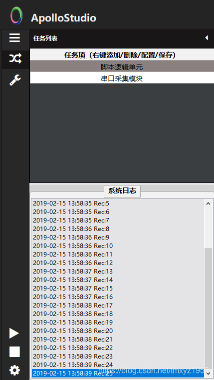
while True:AS.Func_SerialDataSendList(0, str(n) + "\n")#每次先把n转换成字符串后添加换行符发送至序号为0的串口n+=1#发送完成后自动加1,使每次发送内容不同time.sleep(0.2)#延迟0.2秒AS.Func_SysInfoAdd("Rec:" + AS.Func_SerialDataGetList(0))#显示在系统信息栏
点击运行后,即可看到运行结果:
锋芒初露
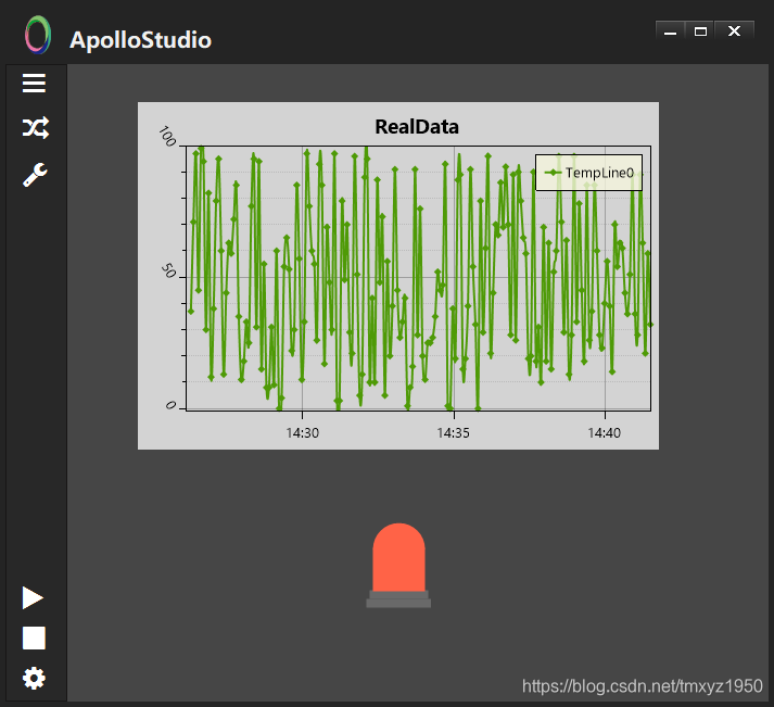
沿用官方的例子或许让各位玩家不尽兴,我们可以在上面的基础上稍微修改下,让Arduino模拟采集数据后,将数据进行上传并在ApolloStudio里面呈现出来(这里我们模拟发送温度数据生成温度曲线,当温度超过临界值时,报警灯报警闪烁)。
Arduino这边我们修改为获取随机数后上传,这里是随机上传0~100的数据:
void setup() {Serial.begin(9600);//串口波特率
}void loop() {Serial.println(random(0, 100));//发送随机数delay(1000);//每次发送延时1秒
}
在ApolloStudio中,我们添加两个控件:图表控件,报警灯,并且分别命名为pv1和led1。
修改脚本如下:
#-*- coding: UTF-8 -*-
#加载内嵌模块
import clr,sys,time,datetime#初始化曲线模型为折线图,默认生成1条折线
AS.Func_UI_PlotView_RT_SetDispModel("pv1", "RealData", 1)#循环函数体
while True:myrec = AS.Func_SerialDataGetList(0)#获取Arduino上传的数据缓存if myrec != "":#过滤掉上传的空数据AS.Func_UI_PlotView_RT_AddPoint("pv1", 0, float(myrec))#添加到折线图上if float(myrec) > 80:#这里限定值为80,超过则报警灯闪烁AS.Func_UI_LanternAlarm_SetValue("led1", True)#闪烁else:AS.Func_UI_LanternAlarm_SetValue("led1", False)#停止闪烁time.sleep(5)#数据采样间隔,这里是5秒便于观察报警灯的状态
注释里面已经详尽讲述了流程含义,下面我们在主界面添加组态界面单元,加载我们在组态UI设计器中设计的UI文件:
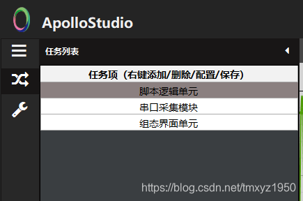
点击运行键,我们即可以看到运行结果:
***********************************************************************************************************************************************
ApolloStudio最新版下载地址(网盘有交流群号):
(点击跳转至首页文章,见文章最底部下载链接)